

Today, in order for a device to fully function there are a lot of smaller devices join the whole. One of these is the PCB or also known as the Printed Circuit Board. A PCB is a small board composed of fiberglass, composite epoxy, or other laminate stuff. Conductive pathways are etched or “printed” onto the board, combining various elements on the PCB, such as semiconductors, resistors, and open circuits.
PCBs are utilized in both desktop and laptop computers. They work as the basis for various internal computer parts, such as video cards, controller cards, network interface cards, and development cards. These segments all relate to the motherboard, which is also a published circuit board. To know more important things about PBC an individual may visit the link https://www.hemeixinpcb.com/TurnkeyPCBAssembly/TurnkeyPCBAssembly.html.
The Basics Of PCB Design: Components and Construction
The Layers of a PCB. The single PCBs are only sided boards (one copper layer). But, the copper traces can also be placed on both surfaces of the board, forming a double-sided PCB. They become more and more difficult as new layers are attached to the original design. These new layers have their own copper trace formations. The copper connections cannot meet one another without the track of the electrical load being settled, so multi-layered PCBs become needed for excellent electronics. However, in the single-sided boards, one side is kept for the copper trace and the other side houses the elements. On top of the copper, layer remains the solder protection and the silkscreen.
The solder cover is what gives the PCB its recognizable green color. This has the purpose of protecting the copper from any metal particles that strength inadvertently come into connection with it. Yet, parts of the metal will continue shown so that they can be joined to. The silkscreen rests on top of the solder mask again. This has words and numbers painted on it which execute the parts of the PCB carefully for the engineer. People may know how to install it properly by searching from this link https://www.hemeixinpcb.com/RigidFlexPCB/RigidFlexPCB.html.
The Components
- The battery stores the voltage to the circuit.
- Resistors, check the electric current as it moves through them. They’re color coded to define their value.
- LEDs a light emitting diode. Lights up when current passes through it, and will only provide current to move in one direction.
- Transistor increases the charge.
- Capacitors these are elements which can hide electrical charge.
- Inductor properties charge and ends and innovation in the current.
- The diode provides current to pass in one direction only, preventing the other.
- Switches can either support current or block depending if they are shut or open.
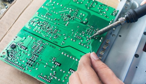
PCB Assembly. The components can be added to the board in different ways. In common, an engineer will decide to apply either the surface mount method or the through-hole process to fasten the components. Following a schematic design and working the numbers on the silkscreen, the engineer practices solder to connect the components to the board. The engineer must be very cautious when patching. As solder is a metal that an engineer decreases so that they can handle it. Any stray blobs that are outside of place and touch other metal parts could make the circuit to short. This can be risky, causing fires or even small bursts. When the components are placed correctly, the PCB is ready to be used in a device. The most important things people need to know for safety purposes.